This month I participated in the measurement of soil respiration using the pp system (EGM5 Carbon dioxide analyzer), in the Lab of Climate and Soil Biogeochemistry, Tennessee State University. I found this procedure very fascinating and I would be sharing a brief description of this procedure and a background on soil respiration.
Interestingly, over 2,700 Gigatonnes (Gt) of carbon is stored in soils worldwide, which is more than three times the amount of carbon in the atmosphere, animals, and plants. However, the soil releases about 60 billion tons of carbon into the atmosphere each year, which is far more than that released by burning fossil fuels. Warming studies have shown that rising temperatures leads to an increase in the rate of soil respiration. As a result, scientists have worried that global warming would increase the decomposition rate of carbon in the soil, releasing more carbon dioxide into the atmosphere and accelerating global warming. Temporary increases in soil respiration induced by certain management practices can also have a negative impact on soil organic matter. Various soil respiration rates respond to various soil management measures differently. Thus, there is a need to measure soil respiration rates to enable better recommendation of management practices.
The CO2 analyzer is used for ambient CO2 monitoring, soil CO2 efflux, global change studies, bioremediation amongst a host of other applications. An image of a conventional CO2 analyzer is shown in figure 1.
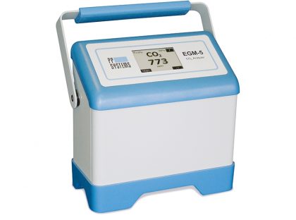
Fig 1: EGM5 Carbon dioxide analyzer
The CO2 analyzer comes with a sampling injection kit as shown in figure 2
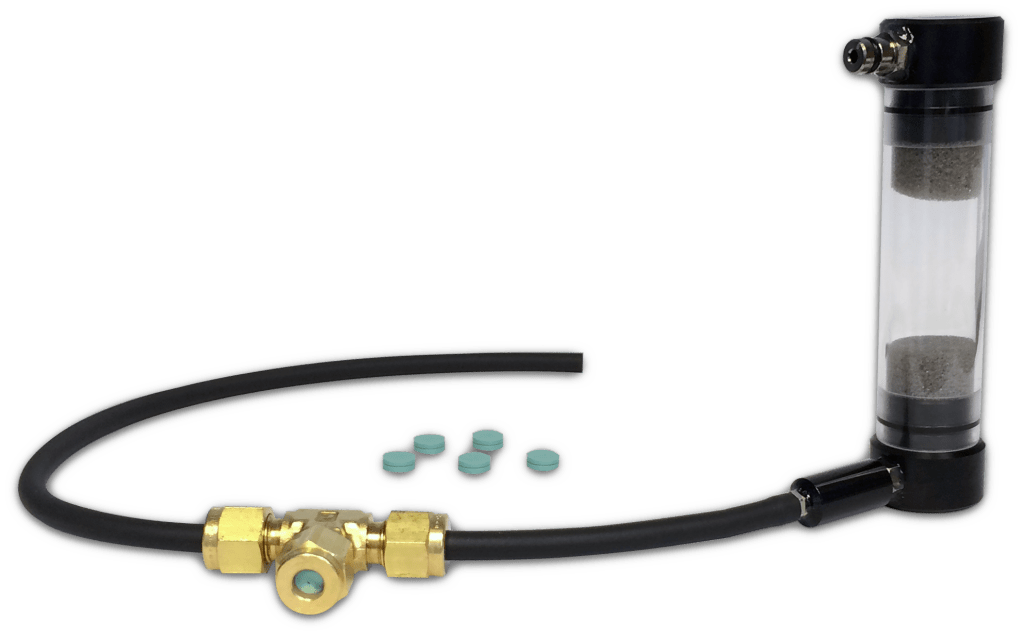
Fig 2: Sampling injection kit
The Procedure for measuring soil respiration
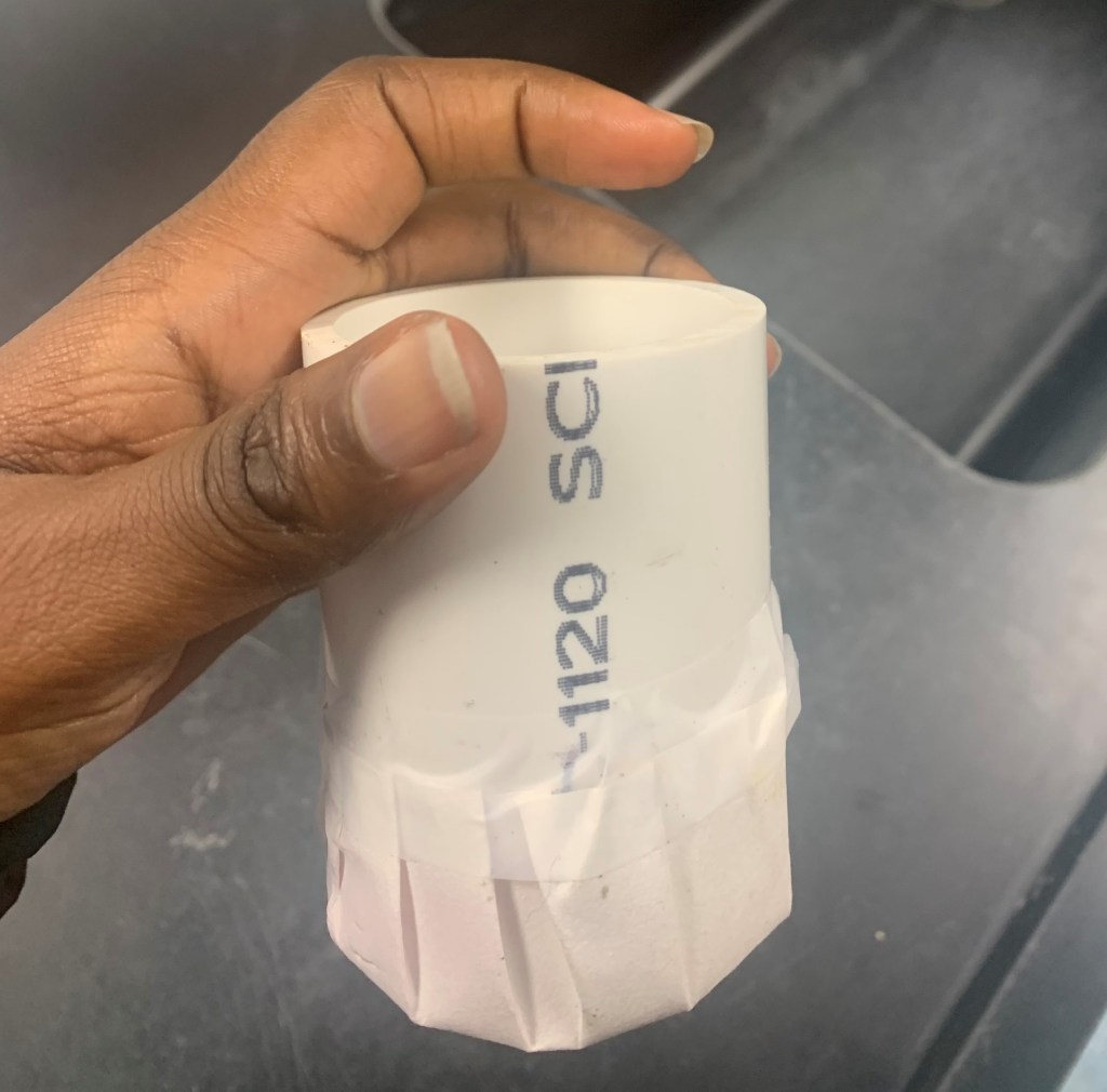
Fig 3: Filter paper sealed in PVC core
First, the filter paper is sealed to a polymerizing vinyl chloride (PVC) core and soil sample of 15 grams is placed into this core as shown above.
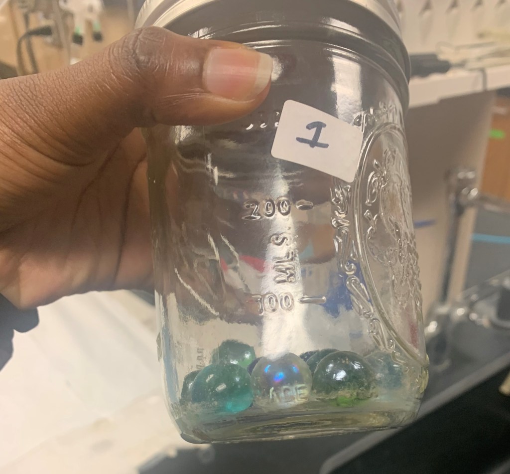
Fig 4: Pebbles in a wide-mouth mason jar
Next, pebbles are added to a wide-mouth mason jar and the PVC containing the soil sample are placed into the jar as seen in the image above.
The jar is sealed with a cover that has a lid that can be perforated in the center of the lid. The jar is then placed in a chamber for six weeks at a constant temperature of 15℃ (The aim is to measure the soil respiration rate at a constant temperature for six weeks in comparison to other studies not for the scope of this description)
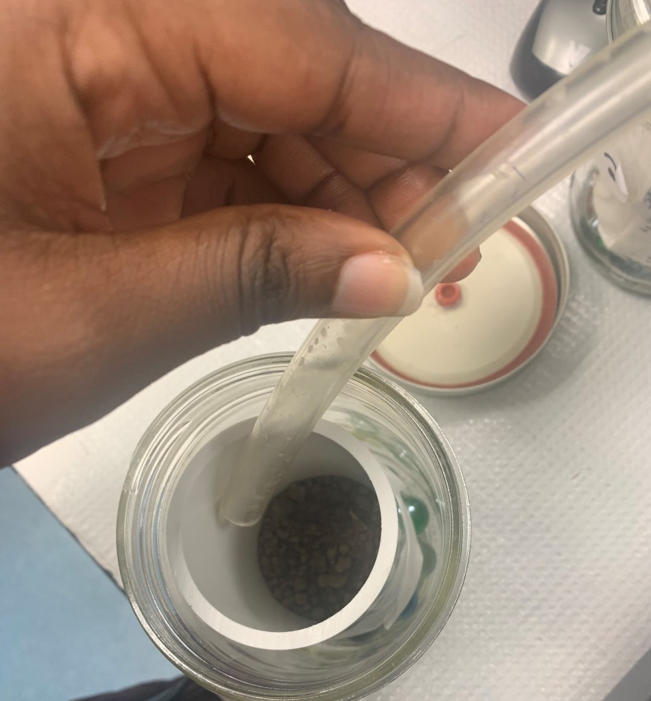
Fig 5: Illustrates the aeration of the sample in the PVC core
The jar is brought out of the chamber weekly to measure soil respiration. Thus, I opened the jars and flushed with air for 8 minutes as shown in the image above.
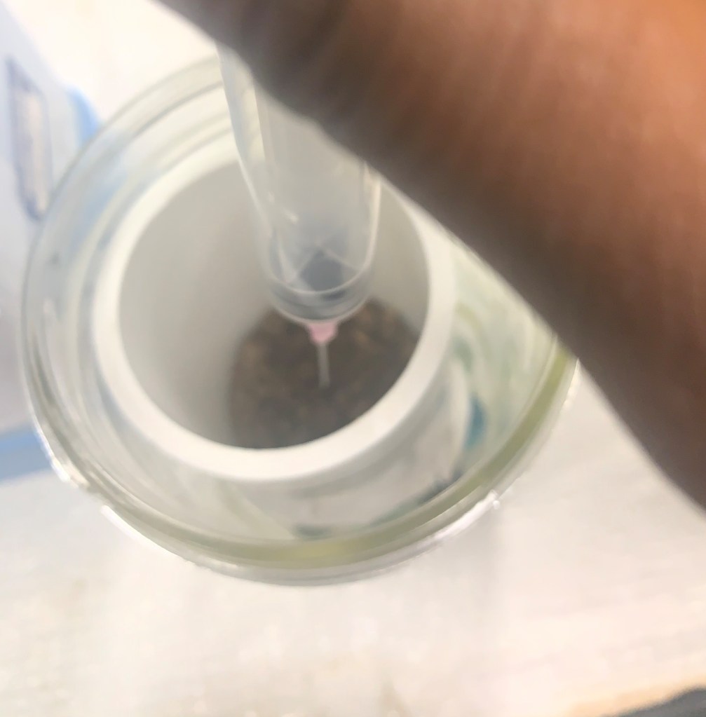
Fig 6: Illustrates the collection of air from the sample using a syringe
As pictured above, a syringe is used to draw air from each jar.
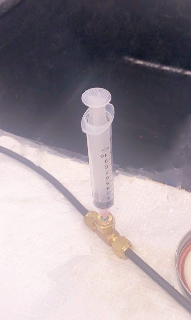
Fig 7: Injection of the air sample into the CO2 analyzer
The carbon dioxide analyzer is turned on and the sample in the syringe is then placed into the sampling pump of the carbon-dioxide analyzer. Afterwards, the CO2 analyzer is then set to read the measurement.
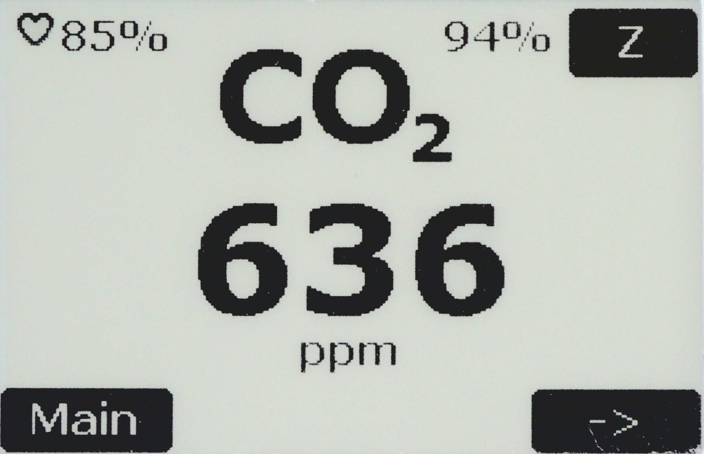
Fig 8: An example of CO2 analyzer display of the CO2 concentration
The main Carbon dioxide measurement screen of the EGM5 C02 analyzer
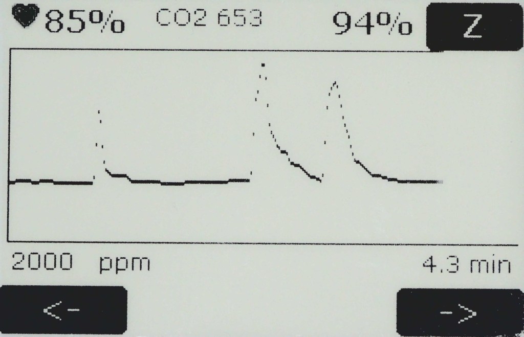
Fig 9: The screen monitor of Carbon dioxide trends and flux rate upon reading from the injection of the sample into the sampling pump.
The EGM5 carbon dioxide analyzer helps to monitor carbon dioxide trends and flux rates. Measuring soil respiration rate is easy and not technical especially when using portable analyzers such as the PP systems. Soil respiration measurements using the pp system can be done both in the field and in the laboratory. If you have measured soil respiration rates what methods did you use? Share in the comments below

Cool stuff! Will you be using this with the switchgrass field?
LikeLike
Yes the experiment will be conducted from switchgrass field plot
LikeLiked by 1 person